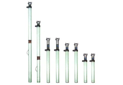

Calculating the load - bearing capacity of a hinged top beam is a crucial aspect in construction and engineering projects. As a supplier of hinged top beams, I understand the significance of this knowledge for both contractors and engineers. In this blog, I will guide you through the process of calculating the load - bearing capacity of a hinged top beam, providing scientific and practical insights.
Understanding the Hinged Top Beam
A hinged top beam is a structural element commonly used in construction, especially in roof structures. It is designed to provide support and stability while allowing some flexibility at the hinge point. This flexibility can be beneficial in accommodating small movements and reducing stress concentrations. Compared to Non - hinged Top Beam, the hinged top beam has unique load - distribution characteristics.
Factors Affecting Load - Bearing Capacity
-
Material Properties
- The material of the hinged top beam plays a vital role in determining its load - bearing capacity. Common materials include steel, wood, and concrete. For example, steel has high strength and good ductility, which allows it to withstand large loads without significant deformation. The yield strength and ultimate strength of the material are key parameters. If we are using a steel hinged top beam, we need to know its yield strength, which is the stress at which the material begins to deform plastically.
- The modulus of elasticity of the material also affects the beam's behavior under load. A higher modulus of elasticity means that the beam will deform less under a given load.
-
Geometric Properties
- The cross - sectional shape and size of the beam are important. A beam with a larger cross - sectional area generally has a higher load - bearing capacity. For instance, an I - shaped cross - section is commonly used in steel beams because it provides high strength with relatively less material. The moment of inertia of the cross - section is a critical geometric property. It measures the beam's resistance to bending. A larger moment of inertia means that the beam can resist bending more effectively.
- The length of the beam is another factor. Longer beams are more likely to experience larger deflections and bending moments under the same load compared to shorter beams.
-
Load Types


- There are different types of loads that a hinged top beam may be subjected to, including dead loads, live loads, wind loads, and seismic loads. Dead loads are the permanent loads, such as the weight of the beam itself, roofing materials, and any attached equipment. Live loads are the variable loads, like the weight of people, furniture, or snow. Wind loads act on the structure from the outside and can cause lateral forces on the beam. Seismic loads are due to earthquakes and can induce complex dynamic forces.
Calculation Methods
Step 1: Determine the Loads
-
Dead Load Calculation
- First, calculate the weight of the beam itself. If the beam is made of steel, we can use the density of steel (approximately 7850 kg/m³) and the volume of the beam to find its weight. For example, if the beam has a cross - sectional area (A) and length (L), the volume (V = A\times L), and the weight (W_{beam}=\rho gV), where (\rho) is the density, (g) is the acceleration due to gravity ((g = 9.81m/s²)).
- Then, add the weight of any attached roofing materials or other permanent fixtures.
-
Live Load Calculation
- Refer to the relevant building codes to determine the appropriate live load for the specific application. For a residential roof, the live load may be around 1.5 - 2.0 kN/m², while for a commercial building, it could be higher. Multiply the live load per unit area by the area supported by the beam to get the total live load on the beam.
-
Wind and Seismic Loads
- Wind loads are calculated based on the wind speed, the shape and orientation of the structure, and the local wind zone. Seismic loads are determined according to the seismic zone of the location and the structural characteristics of the building. These calculations are more complex and often require the use of specialized software or detailed engineering analysis.
Step 2: Analyze the Structural System
- Idealize the Beam as a Structural Model
- A hinged top beam can be modeled as a simply supported beam with a hinge at one or both ends. In a simply supported beam, the reactions at the supports can be calculated using the equations of equilibrium. For a beam with a uniformly distributed load (w) (total load divided by the length of the beam) and length (L), the reactions at the two supports (R_1) and (R_2) are equal and given by (R_1 = R_2=\frac{wL}{2}) if the load is symmetrically distributed.
- Calculate the Bending Moment and Shear Force
- The bending moment (M) and shear force (V) at different points along the beam can be calculated using the equations of equilibrium. For a simply supported beam with a uniformly distributed load (w), the maximum bending moment occurs at the mid - span and is given by (M_{max}=\frac{wL^{2}}{8}), and the maximum shear force occurs at the supports and is (V_{max}=\frac{wL}{2}).
Step 3: Check the Beam's Capacity
- Bending Capacity Check
- The bending stress (\sigma) in the beam is related to the bending moment (M) by the formula (\sigma=\frac{M y}{I}), where (y) is the distance from the neutral axis of the cross - section to the outermost fiber and (I) is the moment of inertia of the cross - section. The allowable bending stress (\sigma_{allow}) is determined based on the material properties. We need to ensure that (\sigma\leqslant\sigma_{allow}).
- Shear Capacity Check
- The shear stress (\tau) in the beam is related to the shear force (V). For a rectangular cross - section, the average shear stress (\tau=\frac{V}{A}), where (A) is the cross - sectional area. Similar to the bending stress, we need to ensure that the shear stress is less than the allowable shear stress (\tau_{allow}).
Special Considerations for Hinged Top Beams
- Hinge Behavior
- The hinge in a hinged top beam allows for rotation, which means that the bending moment at the hinge point is zero. This affects the distribution of bending moments and shear forces along the beam. When analyzing the beam, we need to take this into account when applying the equations of equilibrium.
- Connection Strength
- The connection at the hinge point must be strong enough to transfer the forces. The bolts, welds, or other connection elements should be designed to withstand the shear and axial forces acting at the hinge.
Example Calculation
Let's assume we have a steel Metal Long Beam with a rectangular cross - section of width (b = 100mm) and height (h = 200mm), and length (L = 6m). The beam is simply supported at both ends and is subjected to a uniformly distributed dead load (w_d=1kN/m) and a live load (w_l = 2kN/m).
- Total Load Calculation
- The total uniformly distributed load (w=w_d + w_l=1 + 2=3kN/m).
- Reaction Forces
- Using the equations of equilibrium for a simply supported beam, the reactions at the two supports (R_1 = R_2=\frac{wL}{2}=\frac{3\times6}{2}=9kN).
- Bending Moment Calculation
- The maximum bending moment (M_{max}=\frac{wL^{2}}{8}=\frac{3\times6^{2}}{8}=13.5kNm).
- Section Properties
- The moment of inertia of a rectangular cross - section (I=\frac{bh^{3}}{12}=\frac{0.1\times0.2^{3}}{12}\approx6.67\times10^{-6}m^{4}). The distance from the neutral axis to the outermost fiber (y=\frac{h}{2}=0.1m).
- Bending Stress Calculation
- The bending stress (\sigma=\frac{M_{max}y}{I}=\frac{13.5\times10^{3}\times0.1}{6.67\times10^{-6}}\approx202.4MPa). If the allowable bending stress of the steel is (\sigma_{allow}=250MPa), the beam is safe in terms of bending.
Conclusion
Calculating the load - bearing capacity of a hinged top beam is a multi - step process that involves understanding the material and geometric properties of the beam, determining the loads acting on it, analyzing the structural system, and checking the beam's capacity against the allowable stresses. As a supplier of Double Hole and Double Wedge Top Beam and other hinged top beams, I am committed to providing high - quality products that meet the engineering requirements. If you are involved in a construction project and need to source hinged top beams, or if you have any questions regarding load - bearing capacity calculations, feel free to reach out for a procurement discussion. We can work together to ensure that your project is a success.
References
- "Mechanics of Materials" by Ferdinand P. Beer, E. Russell Johnston Jr., John T. DeWolf, and David F. Mazurek.
- Building codes and standards relevant to structural design in your region.